 English
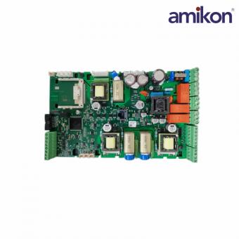
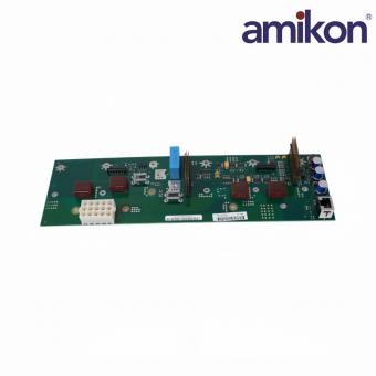
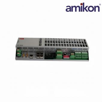
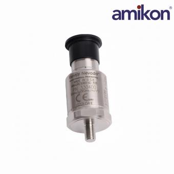
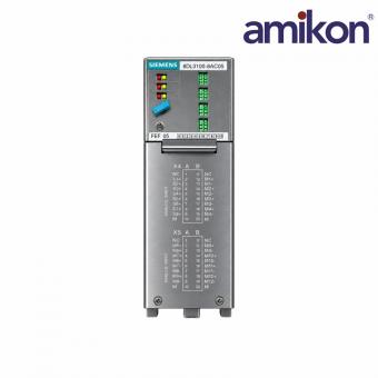
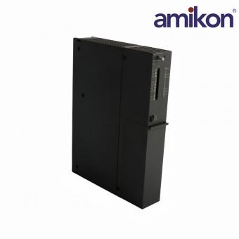
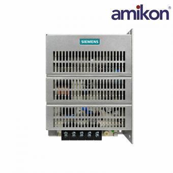
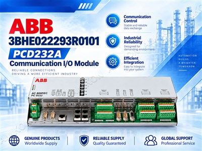
UNITROL · MAINTENANCE & REPLACEMENT BRIEF ABB 3BHE022293R0101 PCD232A Communication I/O Module: Why Interface Verification Comes First A practical guide to identifying the PEC80-CIO device, checking installed interfaces and preparing a model-specific replacement inquiry. PCD232A at a Glance: Combined I/O for UNITROL Systems A replacement request for ABB 3BHE022293R0101 PCD232A Communication I/O Module should begin with the installed label and the system drawings—not with connector appearance. The ABB-authored PC D232 A01 data sheet identifies this order code as PEC80-CIO / PC D232 A0101, a combined digital and analog I/O device generally used in UNITROL 6000 systems. View the historical ABB data sheet ↗ For maintenance teams, the practical question is whether the replacement matches the application, firmware, wiring and communication settings already in service. A shared family name does not establish interchangeability. Module at a Glance 01 · IDENTITY PEC80-CIO PC D232 A0101 02 · DIGITAL I/O 12 DI / 16 relays 24/48 V input groups 03 · ANALOG I/O 3 AI / 3 AO Bipolar signal ranges 04 · SUPPLY 24 V DC Redundant inputs Technical Reference: Check Against the Installed Revision The values below are from ABB data sheet 3BHS224075E02, July 2007. They are reference values for the documented device, not a substitute for current project documentation. Parameter Specification Power & Environment Supply range 20–28 V DC Maximum supply current 2 A Operating temperature −25 to +70°C Signal Interfaces Analog inputs ±10 V or ±20 mA Analog outputs ±10 V Temperature inputs 3 PT100/PTC interfaces Communication Ethernet 4 ports, 10/100 Mbps Panel interface RS232 Other interfaces RS485 Modbus and CAN Optical module 3 optical links Service Check Before installation Verify revision, address, application software and redundant configuration. A More Useful Replacement Workflow 0101 · IDENTIFY Photograph the complete label and record the installed revision. 0202 · MAP Compare terminal assignments, signal types and network settings with the drawings. 0303 · VERIFY Have qualified site personnel confirm application and commissioning requirements. When a communication alarm or intermittent signal appears, record the fault context before disconnecting anything. Useful evidence includes status indications, the affected channel, recent wiring changes, supply measurements and the configured network path. This evidence helps distinguish a module issue from a field-device, cabling or configuration problem. Engineering caution: Generator-excitation maintenance must follow the site’s isolation and commissioning procedures. This article is not an installation instruction or an assurance that a replacement is plug-and-play. Where PCD232A Fits in Maintenance Planning A PCD232A replacement decision should connect the installed hardware identity with the plant’s drawings, configured interfaces and maintenance evidence. Use the three checks below to prepare a clearer review before...
Read More



 IPv6 network supported
