 English

Predictive analytics can identify patterns only after the measurement chain has produced trustworthy shaft data. The Bently Nevada 330180-51-00 remains important because reliable decisions still begin at the physical interface between the machine and the monitoring system.
AI-enabled control rooms promise earlier warnings, fewer unplanned outages and better maintenance priorities. Yet every algorithm is downstream of a sensor chain. If the probe system is mismatched, the gap is wrong, the cable length is incorrect or the installed hardware identity is uncertain, the resulting trend may look precise while describing the wrong physical condition. That is why vibration-data quality remains an engineering issue before it becomes a software issue.
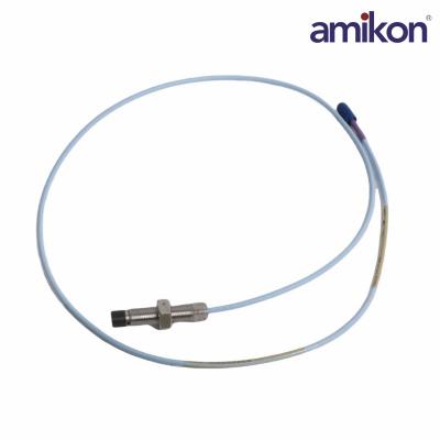
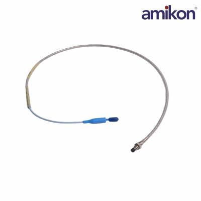
In a 3300 XL 8 mm proximity transducer system, the measurement does not begin in a dashboard. It begins at the rotating shaft. The complete chain includes the 3300 XL 8 mm probe, extension cable and Proximitor Sensor. The system output is proportional to the distance between the probe tip and the observed conductive surface, enabling both static position and dynamic vibration measurement.
The standard 5 m 3300 XL 8 mm system is documented by the manufacturer as meeting API 670 requirements for mechanical configuration, linear range, accuracy and temperature stability. This is a system-level statement: performance depends on the compatible chain, not on treating one component as an isolated universal converter.
A probe, cable and Proximitor Sensor selected for different total system lengths can alter the expected response.
Incorrect probe gap, target material, mounting stability or cable routing can distort the signal before software receives it.
A familiar-looking module may have different length, mount or approval options hidden in its suffix.
Missing baseline values, calibration context and replacement history make a clean-looking trend harder to trust.
| AI and analytics can help | The field measurement chain must provide |
|---|---|
| Detect trend changes and relationships | A stable, correctly scaled signal from compatible components |
| Rank anomalies for investigation | Correct installation, gap and target conditions |
| Compare operating states across time | Traceable asset identity and maintenance history |
| Support maintenance prioritisation | Engineering validation before a machine decision |
01 · Confirm total system length.
Verify that the installed probe, extension cable and Proximitor Sensor belong to the intended 5 m system configuration.
02 · Confirm mounting.
Option 51 specifies DIN mounting. Review the cabinet arrangement, available space and connector access.
03 · Confirm the approval requirement.
Suffix 00 denotes no agency approvals. Do not assume suitability for a classified area without reviewing current site requirements and manufacturer documentation.
04 · Preserve the operating evidence.
Record gap voltage, machine state, channel configuration, alarm context and the reason for replacement before disturbing the installed chain.
No. It is a 3300 XL Proximitor Sensor. A complete system also includes the compatible 8 mm probe and extension cable.
It identifies a 5.0 metre total system length and DIN-mount format. Confirm both points against the installed arrangement.
Potential interchangeability depends on the exact compatible 3300 XL chain and installation condition. Verify the full probe, cable and sensor identity and follow the current manufacturer guidance before return to service.
No. Option 00 is the version without agency approvals. The site must separately confirm any certification requirement.
Consistent data can still be systematically biased by mismatched components, installation geometry or incorrect scaling. Smoothness is not proof of measurement validity.
Send the complete part number, photos of the label and mounting, probe and extension-cable identities, quantity, condition requirement, destination and target delivery date.
Follow the approved site procedure to verify mechanical installation, gap, channel response, alarm configuration, baseline data and return-to-service documentation.
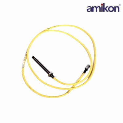
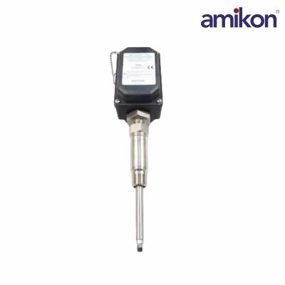
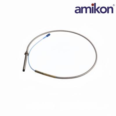
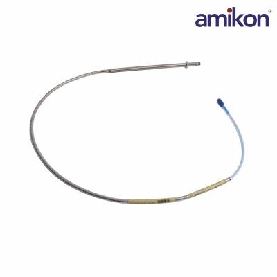
Explore recently published Bently Nevada proximity-system components. Open each card to review the product details and confirm the exact part number before enquiry.
For Bently Nevada 330180-51-00, disciplined part-number verification and complete-system thinking remain essential to trustworthy vibration monitoring and predictive maintenance.
Technical identity and system descriptions should be checked against the current manufacturer documentation before specification or installation. Reference: Baker Hughes Bently Nevada proximity sensors and the 3300 XL 8 mm Proximity Transducer System datasheet.
Bently Nevada and Baker Hughes are trademarks of their respective owners. This independent article is for product-identification and lifecycle-planning reference only; always use current official documentation and approved site procedures.

Get regular updates and real automation insights straight to your inbox.


 IPv6 network supported
Disclaimer: Amikon sells new and surplus products and develops channels for purchasing such products. This website has not been approved or recognized by any of the listed manufacturers or trademarks. Amikon is not an authorized distributor, dealer, or representative of the products displayed on this website. All product names, trademarks, brands, and logos used on this website are the property of their respective owners. The description, explanation, or sale of products with these names, trademarks, brands, and logos is for identification purposes only and is not intended to indicate any association with or authorization from any rights holder.