 English
A practical technical and procurement guide for engineers expanding, maintaining or replacing mixed 24 V DC I/O in SIMATIC S7-1200 control systems.
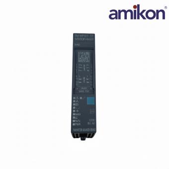
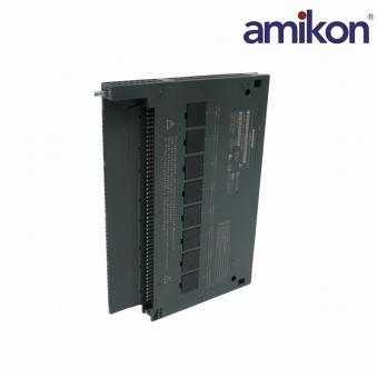
The Siemens 6ES7223-1BH32-0XB0 is a SIMATIC S7-1200 SM 1223 digital input/output signal module. It combines eight 24 V DC digital inputs with eight 24 V DC transistor outputs in one expansion unit. For compact machines and localized control panels, that balanced channel count can reduce module quantity while keeping sensor feedback and actuator commands together.
Its value is not only the 16 total signal points. Correct selection depends on output technology, current limits, field wiring, external circuit protection and the available S7-1200 expansion capacity. A module with a similar SM 1223 description may still have a different channel count or relay outputs, so the complete article number matters.
The module is an SM 1223 mixed digital signal module for the S7-1200 platform. It receives discrete 24 V DC field states from switches and sensors, then switches compatible 24 V DC loads through transistor outputs. It is not a CPU, safety module or relay-output module.
| Technical Item | Specification |
|---|---|
| Article number | 6ES7223-1BH32-0XB0 |
| Product family | SIMATIC S7-1200, SM 1223 |
| Digital inputs | 8 channels, 24 V DC, sink/source; IEC 61131 Type 1 |
| Digital outputs | 8 transistor outputs, 24 V DC |
| Output current | 0.5 A maximum per output |
| Permissible supply range | 20.4 to 28.8 V DC |
| Backplane bus current | 145 mA maximum at 5 V DC |
| Typical power loss | 2.5 W |
| Output switching delay | 50 microseconds rising; 200 microseconds falling |
| Cable length | Shielded up to 500 m; unshielded inputs 300 m; unshielded outputs 150 m |
| Diagnostics | Diagnostic alarm and channel-status LEDs |
| Protection degree | IP20 |
Many compact machines need a similar number of field inputs and control outputs. Eight inputs can monitor devices such as limit switches, selector switches, push buttons and proximity sensors. Eight outputs can command compatible indicator lamps, interface relays, small solenoid valves and contactor coils. Combining both directions in one module can conserve DIN-rail space and simplify the bill of materials.
Input and output status LEDs provide a fast visual check during startup and troubleshooting. Technicians can compare the PLC program state with the physical channel indication before moving deeper into field wiring, load or logic diagnostics.
The transistor outputs are intended for 24 V DC loads. Applications requiring dry contacts, AC switching or electrical isolation through relay contacts may need a different SM 1223 version or external interface relays. The 0.5 A channel limit must also be checked against steady-state and inrush current.
Typical applications include packaging and filling equipment, conveyor systems, compact assembly machines, process skids, machine-tool auxiliaries, utility panels and production-line interlocks. It is especially practical where a local machine section requires both sensor feedback and DC actuator control.
Confirm the field supply first, then compare the program command with the output LED and terminal voltage. Check load polarity, current demand, wiring continuity and external protective devices. A lit channel LED does not by itself prove that the field load is correctly powered or wired.
Loose terminations, incorrect sink/source wiring, inadequate reference potential, electrical noise or cable routing near high-energy conductors can create intermittent states. Use the specified cable practices and verify grounding, shielding and field-voltage stability at the module terminals.
The Siemens 6ES7223-1BH32-0XB0 is a practical way to add balanced digital I/O to an S7-1200 system. Its eight 24 V DC inputs, eight 0.5 A transistor outputs and clear status indication suit many compact automation tasks. Reliable replacement, however, depends on verifying the complete part number, output technology, field supply, wiring and external protection rather than relying on physical appearance alone.
Send the exact model 6ES7223-1BH32-0XB0, quantity, destination and required delivery date to the Amikon sales team for an availability review. Add the installed CPU and a nameplate photo when replacement compatibility needs to be checked.
|
L
Sales Manager
Lisa Lin
|
WA
WhatsApp
|
@
Email
|
Technical basis: Siemens Industry Mall and Siemens SIMATIC S7-1200 SM 1223 technical data. Final installation and commissioning must follow the current Siemens documentation and applicable site requirements.

Get regular updates and real automation insights straight to your inbox.


 IPv6 network supported
Disclaimer: Amikon sells new and surplus products and develops channels for purchasing such products. This website has not been approved or recognized by any of the listed manufacturers or trademarks. Amikon is not an authorized distributor, dealer, or representative of the products displayed on this website. All product names, trademarks, brands, and logos used on this website are the property of their respective owners. The description, explanation, or sale of products with these names, trademarks, brands, and logos is for identification purposes only and is not intended to indicate any association with or authorization from any rights holder.