DeltaV S-Series PROFIBUS DP: Fieldbus Hardware and Maintenance for KJ3243X1-BK1 / SE4022 / 12P4691X042
When a PROFIBUS DP device stops updating, replacing the interface card may appear to be the quickest solution. However, the communication path also includes the terminal assembly, fieldbus wiring, device configuration and the field device itself.
For maintenance and purchasing teams working with KJ3243X1-BK1 / SE4022 / 12P4691X042, the practical question is therefore specific: which part of the installed connection needs attention, and what exactly should the replacement supply include?
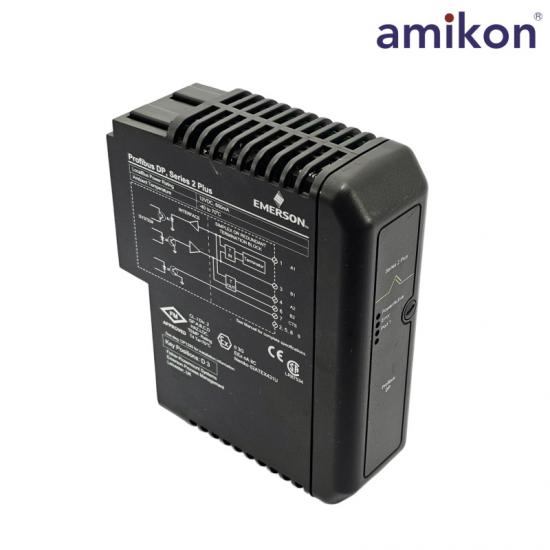
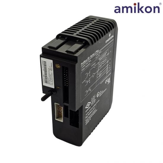
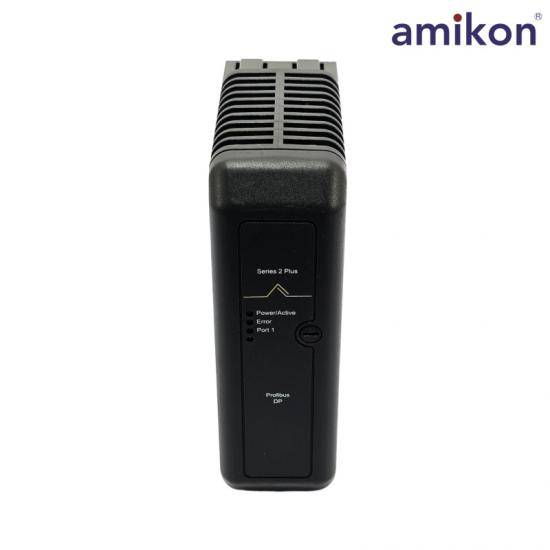
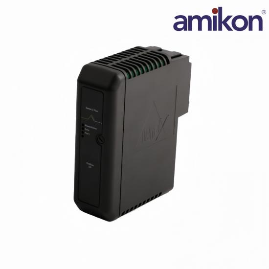
Browse the product photographs and ordering checks with the arrows. Related catalogue models require a separate compatibility review for the installed system.
Keep KJ3243X1-BK1, SE4022 and 12P4691X042 together in the enquiry. Define whether the required supply covers the interface card, terminal hardware or complete assembly.
Ordering check
Match the installed label, terminal arrangement and requested supply scope.
AMIKON lists KJ3243X1-BB1 12P3994X052 VE4022 as a PROFIBUS DP Series 2 Plus interface card. Use the complete installed reference when asking for the exact part.
Ordering check
Confirm the installed hardware generation and terminal configuration separately.
AMIKON also lists KJ3243X1-BB2 as a Plus PROFIBUS DP card. Include clear label photographs and the existing system details when preparing a model-specific enquiry.
Ordering check
Confirm the full label reference, system release and required termination hardware.
The three references belong together in the purchasing record, but they serve different identification purposes.
ReferenceHow to use it during procurement
CARD MODEL
KJ3243X1-BK1
Record the interface-card model.
ORDER CONFIGURATION
SE4022
Check the required order configuration and termination-block supply scope.
COMPLETE PART REFERENCE
12P4691X042
Preserve the complete part reference shown on the requested or installed unit.
Emerson’s published ordering list describes SE4022 as a simplex PROFIBUS DP I/O interface supplied with a termination block. Consequently, an enquiry for an SE4022 assembly should state whether the customer requires the complete assembly or a card-only replacement. Emerson ordering reference
A quotation should identify the supplied components individually. Photographs of the installed card and terminal assembly help purchasing and engineering teams review the same requirement.
02
MAP THE HARDWARE
Separate the Interface Card from the Terminal Assembly
The installed connection can be represented as:
DeltaV system → S-Series PROFIBUS DP interface → Terminal assembly → PROFIBUS segment → Field devices
SYSTEM CONTEXT
Record the installed environment.
Keep the relevant DeltaV release and hardware arrangement with the maintenance record.
INTERFACE IDENTIFICATION
KJ3243X1-BK1
Preserve SE4022 and 12P4691X042 in the purchasing request, together with the required supply scope.
Review where the terminal block sits on the segment before checking the IN / OUT termination position.
DEVICE CONFIGURATION
Keep the device details.
Record model, revision, station address, GSD identification and assigned input/output data.
TERMINATION EXPLORER
Where is the terminal block?
Select a location
DEVICEField node
DEVICEField node
THIS TERMINALSegment endIN
IN
A terminal block at the segment end uses the IN termination position in the documented configuration.
DEVICEField node
THIS TERMINALMiddle positionOUT
DEVICEField node
OUT
A terminal block in the middle of the segment uses OUT in the documented configuration.
Conceptual layout only. Confirm the complete installed hardware and approved segment drawing.
Emerson’s S-Series hardware reference identifies KJ4006X1-BQ1 as the PROFIBUS DP terminal block and KJ4006X1-BR1 as the redundant PROFIBUS DP terminal block.
The terminal hardware also provides a selectable bus-termination arrangement. In the documented configuration, a terminal block at the segment end uses the IN termination position; a block in the middle of the segment uses OUT. The correct setting therefore depends on the installed topology.
These are hardware-reference identifiers, rather than confirmation that a particular terminal assembly is included with an Amikon quotation. Confirm the complete installed part number, revision and application before ordering. Hardware reference: Emerson D800040X162, DeltaV S-Series and CHARMs Hardware Reference.
For maintenance planning, distinguish terminal connections, which provide the wiring interface, from bus termination, which is a network setting. Replacing one component does not establish that the other is correct.
03
VERIFY CONFIGURATION
Check Field-Device Configuration Before Condemning Hardware
A replacement interface card does not resolve an incorrect device configuration by itself.
DEVICE DESCRIPTIONGSD file
→
DEVICE STRUCTUREModules & I/O
→
PROJECT INTERPRETATIONSignals & units
Emerson explains that a GSD file identifies the device and describes supported rates, timing, available I/O and features. DeltaV uses this information to establish device communication. Official GSD configuration reference ↗
SIX DETAILS TO CAPTURE
Build a configuration record before changing hardware
01
Device identity
Complete field-device model and hardware revision.
02
Network settings
Station address and configured communication settings.
03
GSD identification
The device description file used for the installed hardware version.
04
Modules and slots
Selected device modules or slots, where applicable.
05
Signal interpretation
Input/output data assignments and engineering units.
06
Diagnostic history
Relevant messages and recent configuration or maintenance changes.
WORKED INVESTIGATION / VALUE DISCREPANCY
Communication is available. One value still looks wrong.
Compare the device’s configured data arrangement with the project’s signal assignment and conversion.
STEP 1Read the device data layout
Identify which module, slot and data item represents the required value.
STEP 2Match the project assignment
Compare the received data with the signal configured in the project.
STEP 3Review units and conversion
Check how the received information is converted and displayed.
Engineering review: this is an investigation path. The symptom alone does not establish that the interface card has failed.
What should the handover record retain?
Record the configuration before making changes, then compare the original condition with the eventual result. Keep the device identification, diagnostics and change history together.
04
COLLECT THE EVIDENCE
Use the Fault Pattern to Define the Investigation
The extent of a problem can help organize the evidence collected before a replacement decision.
Observed condition
Choose the fault pattern.
Evidence before replacement
Evidence to collect
Device power, address, local diagnostics and its network connection
Question to resolve
Is the discrepancy limited to that device or connection?
Evidence to collect
Affected stations, segment drawings, shared equipment and event timing
Question to resolve
Which dependencies do the affected devices share?
Evidence to collect
Device data layout, signal assignment, units and scaling
Question to resolve
Is the received information being interpreted correctly?
Evidence to collect
Before-and-after labels, terminal settings, wiring records and configuration changes
Question to resolve
What changed during the intervention?
This framework helps determine where to investigate; it does not assign a confirmed cause from the symptom alone.
For example, a group of devices failing at the same time justifies reviewing their common path. An isolated value discrepancy calls for a more focused comparison of the device data and its configured use.
Purchasing can then work from a documented hardware requirement instead of a general request for “a PROFIBUS card.”
05
SET THE MAINTENANCE BOUNDARY
Define the Boundary Between Maintenance and Internal Repair
The Emerson ATEX57 instruction sheet for KJ3243X1-BK1 specifies 12 VDC at 600 mA LocalBus power and D3 terminal-block keying.
It also establishes important maintenance limits:
01
The unit must not be removed or inserted while system power is energized.
02
Applicable field power must be removed before disconnecting or connecting the device.
03
The card contains no user-serviceable internal parts and should not be disassembled.
04
Routine calibration is not required. Reference: Emerson ATEX57 instruction sheet.
For a maintenance team, this means separating external inspection, configuration review and planned module replacement from internal component repair.
Before removing hardware, capture the relevant identification and diagnostic evidence. After replacement, acceptance should verify communication with the affected devices, the associated process values and the required field response under the site’s approved procedure.
A powered card or a restored communication indication provides useful evidence, but the acceptance record should also address the function the maintenance work was intended to restore.
06
PREPARE THE ENQUIRY
Prepare an Accurate Amikon Enquiry
For KJ3243X1-BK1 / SE4022 / 12P4691X042, send Amikon a requirement that defines both product identity and supply scope.
Include:
If the fault has not yet been isolated, describe the affected devices and provide the available diagnostics. Keep the purchasing requirement distinct from the engineering conclusion about the fault.
Amikon’s dedicated product page provides a direct starting point for reviewing the requested model and submitting an enquiry.
Disclaimer: Amikon sells new and surplus products and develops channels for purchasing such products. This website has not been approved or recognized by any of the listed manufacturers or trademarks. Amikon is not an authorized distributor, dealer, or representative of the products displayed on this website. All product names, trademarks, brands, and logos used on this website are the property of their respective owners. The description, explanation, or sale of products with these names, trademarks, brands, and logos is for identification purposes only and is not intended to indicate any association with or authorization from any rights holder.

 English



 IPv6 network supported